Generating Worms-style Terrain with Simplex Noise
July 26th, 2023
Have you ever played any of the classic 2D Worms games? I enjoyed a number of hectic battles in Worms Armageddon back in the day, but I was always more fascinated by the game’s randomly generated landscapes than by its combat mechanics. A game map in one of those early games might look something like this:

Child me found it immensely fascinating how the game could generate infinite numbers of these landscapes on demand to make every round feel like a fresh challenge, and I wondered how I could do something like that for myself. A few decades later and with a lot more pertinent knowledge under my belt, I would like to take you on a journey to do just that! This article will show you how to procedurally generate Worms-like 2D side view game maps from a blank slate, requiring only basic programming knowledge and that you don’t run away screaming upon the sight of high school level math.
Wanna join me? Here’s where I want us to end up today:
That looks like a reasonable approximation of the 2D side view landscapes we want. Try clicking the image above to generate a few different ones! Not every one of them would necessarily be fun to play in Worms, but to show the principles of how this kind of world generation works, I think it’s a nice goal to aim for.
So how can we come up with a way to generate these landscapes on demand? Before we dive into the approach, let’s try to summarize some requirements.
- The landscapes need to be suitable for side view gameplay, i.e. mostly have air at the top and solid ground at the bottom.
- We want bits like caves, overhangs, and even little floating islands. No need to be realistic or to obey gravity, all it needs is to look fun to jump around on.
- Simultaneously, the landscapes should look reasonably traversable. We want lots of flat and curved surfaces to walk and climb, no giant spikes or tiny hooks to get stuck on.
With these requirements in mind, it becomes easier to judge which tools and methods will bring us closer to our goal. I’ll divide the journey from here into two parts: calculating the shape of our landscape in a pixel grid and deciding which parts are solid and which ones are air (we will be calling it the collision mask), and then turning that into a visually appealing result with cute textures and some basic detailing and shading.
Calculating the Collision Mask
By convention, digital 2D images are usually described and manipulated using a coordinate system that has its origin point in the top left corner, with the x axis going to the right and the y axis going down. This means that any pair of two positive whole numbers (x, y) identifies one single pixel in an image, assuming the numbers are smaller than the image’s dimensions.
Whatever game engine or programming environment you’re using, let’s assume that it gives you a way to create an image and access its pixels one by one to set and get colors at any specific point. So whatever calculation we’re doing, it’ll need to be done for each and every pixel. For this article I’m keeping my example images fairly small at just 500 by 300 pixels, because I want you to be able to experiment with things quickly without dragging down the performance too much, but for your game your images can be a lot larger.
Here’s a basic framework to go over our image pixel by pixel and fill them with something:
for( int x = 0; x < image.width; x++ ) {
  for( int y = 0; y < image.height; y++ ) {
    Array[int] gray = [127, 127, 127];
    image.setPixel(x, y, gray);
  }
}
(The code examples in this article are a sort of C-style pseudocode that I hope are fairly straightforward to adapt to whatever language you’re using.)
Assuming our image contains RGB data with 8 bits per channel, as has been the most common way to store colors for a long time now, each pixel holds three color channels (red, green and blue) with a value between 0 (no intensity) and 255 (full intensity). The color (0, 0, 0) is solid black and (255, 255, 255) is solid white. For now, we’ll be pushing the same values to all three color channels to work in grayscale. The result of the above code would then be a full image of a sort of mid-gray:
Okay, so how should we fill our image?
We already know that we want to be able to generate infinite different random landscapes, so randomness has to enter our code somehow. Let’s just go wild and assign every pixel a random value.
for( int x = 0; x < image.width; x++ ) {
  for( int y = 0; y < image.height; y++ ) {
    int brightness = randomRange(0, 255);
    image.setPixel(x, y, [brightness, brightness, brightness]);
  }
}
This is assuming that randomRange is a function that returns a random integer value from the interval given by its two parameters. With this, every one of the pixels in our image now gets a valid random grayscale value.
This kind of value distribution is called white noise in signal processing, which is an area whose vocabulary we will encounter a few times in this article. It’s not called “white noise” because that’s how we decided to color it, but because every pixel’s individual value is completely unrelated to its neighbors, like photons in white light. If you’d like to learn more, Wikipedia has you covered as usual.
As cool as it looks, unfortunately it’s not super helpful for us. We don’t want to draw TV static after all, we want to create a landscape that has features like hills and caves. For that, we’re going to need a different kind of noise – a kind of noise that’ll give us values which are clumped together more, so we can use them to draw blobby, bulby shapes.
Enter simplex noise! Simplex noise is an algorithm that can generate that kind of blobby noise for us. There’s a whole story about how it works, but I’ll skip the mathematics outright and point you towards Wikipedia again if you feel like digging into it further. For our purposes I’ll just ask you to find a nice library for it (I’m using a modified version of this public domain implementation by Seph Gentle), or if you’re working in a large modern game engine, it might even come with a simplex noise function in its standard library. If it turns out too hard to find one, you can also use Perlin noise instead, it doesn’t make much of a difference for what we’re building here.
Going forward, I’ll assume you have procured a simplex noise function that accepts arbitrary numbers as x and y parameters and outputs values between 0 and 1. If yours is different, you may need to massage the values somehow. For example, some libraries have an output range of [-1;+1], which you’d have to map to [0;1] yourself by adding 1 (which shifts it to [0;2]) and then dividing by 2.
With a simplex noise function ready to go, it’s worth noting that its input is contiguously defined, meaning it accepts fractional numbers for its x and y inputs, and as we’re about to find out, it matters how much we scale the input parameters. We can’t just blindly pass in our pixel coordinates anymore. Instead, let’s calculate relative values for x and y to describe the position in the image as coordinates in the interval [0;1].
for( int x = 0; x < image.width; x++ ) {
  for( int y = 0; y < image.height; y++ ) {
    float xRel = x / image.width;
    float yRel = y / image.width;
    float frequency = 3.0;
    float value = simplex(xRel * frequency, yRel * frequency);
    int brightness = round(255 * value);
    image.setPixel(x, y, [brightness, brightness, brightness]);
  }
}
Okay, there’s a bit more going on there with the frequency stuff, plus the division for yRel looks off if we’re dividing it by the width instead of the height. What’s happening there?
Generally, if we just pass x and y values on a scale between 0 and 1 into our simplex noise function, the result will resemble one big blob. I’m scaling both input parameters by a fixed number, 3 in this case, to squish the value space closer together so we’ll have a bit more to see in our image. In signal processing, this is called frequency because it describes how often we see something within the same range, and we’ll look into it in more depth in a bit. As for the image dimensions, it’s the price I pay for making the example images in this article non-square. If we let xRel and yRel both go from 0 to 1 even though these images are 500 by 300 pixels, the resulting blobs will be vertically squished. That may not be a disaster for our landscapes, but I want you to get a proper idea of what simplex noise looks like, so I’m making sure it’s scaled correctly. As a result of dividing y by the image’s width instead of the height, for the images in this article yRel will only go from 0 to 0.6, which corrects for the aspect ratio.
Alright, that’s a long enough explanation for what gives us the following image:
Your first reaction to seeing simplex noise rendered like this might be, hey, that’s just blurry! And yeah, it totally is. Turns out blurry is what we want. Blurry will be super useful. I promised to keep the math simple for this article, so I’ll just say this: with the value field looking blurry like that, we’ll be able to turn it into smoothly curved landscapes with no weird tiny spikes or jaggies. In this image you can already see the blobby structure of simplex noise in contrast to white noise.
That said, at this point we should remind ourselves that this method of showing noise – rendering it as a grayscale image – is just one possible visualization. What the blurriness means here is that neighboring values form smooth shapes without any sharp drop-offs. Contrary to photography, this blurriness has nothing to do with a lack of clarity. To drive that home, let’s look at a different way to visualize the same field of simplex noise:
Here you have a three-dimensional rendering of the exact same values, only now they’re expressed as mountains for high values and valleys for low ones. If you look closely, you can spot the features from the previous visualization in this one. Because they’re linked, if you click one of them to regenerate it, the changes will be reflected in the other one automatically.
Note that any dark spots you see in this 3D visualization are actual shadows, not low noise values. Dark spots in the 2D visualization correspond to valleys in the 3D one.
In game development, black and white images that serve as templates for the local elevation of a 3D landscape like this are called heightmaps and they’re very useful for 3D terrain. Our simplex noise field is infinitely large in theory, so we could generate as much of this landscape as we want without ever running into errors (or, technically, for a very very long but not quite infinite time). You can probably see how something like this could be used for a Minecraft-like game with infinite mountains to wander through.
But we’re not trying to make Minecraft, we’re trying to make Worms. So let’s keep digging into what we can do with this simplex noise.
As promised, we’ll take a closer look at the frequency. For this next visualization, I’m giving you a slider that lets you manipulate the frequency used to render our simplex noise. By dragging the slider, the frequency as seen in the prior code example can be changed within a range from 0 to 10. I’ll start you off at 3 again (although the exact values really don’t matter too much at this stage) and you can experiment with it.
Alright, cool! So that does something interesting.
As you change the frequency, you can see in the 2D visualization that the size of the noise blobs is changing. Increasing the frequency lets you see more blobs, in exchange for each one of them getting smaller. Because we scale both input parameters by the same value, it looks a lot like we’re zooming out, away from the image. It feels like that because, with a 2D image, scaling it down linearly looks the same as pulling the camera away.
The 3D rendering offers a slightly different perspective on the frequency change. It reminds us that while the scale of the input parameters (x and y directions) is changing, the output range stays the same. Our 2D image still contains shades from all the way black to all the way white, and the 3D rendering keeps the mountains and valleys at the same height as before even while they get squished closer together. And I think the latter is the more useful metaphor for what’s happening, rather than zooming in and out. Think of increasing the frequency as squishing the noise values closer together, like a blanket that gets increasingly crumpled.
For our final landscape, we’ll be able to experiment with the frequency to pick a range that looks good. If you’re building something like this in your own game, the frequency you want will depend on the size of your target image.
Okay, so we can render blurry blobs at whatever size we want. But how do we get from there to an actual collision mask? So far, our output images have contained all sorts of grayscale values, but for our landscapes, there are only two valid collision values: any pixel is either ground or air, there are no in-between states. So we need to transform our blurry grayscale image into one that’s pure black and white. What’s a good strategy to do that?
Here’s an idea: we pick a threshold value somewhere between 0 and 1. For every pixel we render, we check whether the noise value is larger or smaller than the threshold value. If it is smaller, we color the pixel solid black (which we’ll later treat as air), if it is larger or equal – gotta account for exact equality too! – we’ll color the result white and treat it as solid ground.
for( int x = 0; x < image.width; x++ ) {
  for( int y = 0; y < image.height; y++ ) {
    float xRel = x / image.width;
    float yRel = y / image.width;
    float frequency = 3.0;
    float value = simplex(xRel * frequency, yRel * frequency);
    if( value >= 0.5 ) {
      value = 1.0;
    } else {
      value = 0.0;
    }
    int brightness = round(255 * value);
    image.setPixel(x, y, [brightness, brightness, brightness]);
  }
}
The color scheme here is, of course, completely arbitrary. You could pick white as air and black as ground if you prefer, or use completely different colors. Your world is your own! I’m just sticking with this one to keep it uniform throughout the article.
Alright, here’s some simplex noise rendered to solid black and white using a threshold value of 0.5:
On average, we would expect that a threshold value of 0.5 would result in half the image being black and half being white, although outliers are technically possible.
If you’ve done any image editing before, you might realize that what we’ve done here is basically the same as taking a grayscale image and cranking the contrast up to the maximum. Any dark grays get pushed to solid black, any light grays get pushed to full white. And yeah, maximizing the contrast is basically the same process as taking a grayscale image and reducing the color palette to 1 bit (black and white) with the “nearest color” setting. If that means nothing to you, don’t worry about it, it’s just a neat parallel for people who have experience with that aspect of image editing.
So yeah, we could totally use this as a basic collision mask. It doesn’t really look like what we want yet, but at this point we have achieved a blobby-looking randomly generated landscape. Although before calling it done, maybe it’s worth exploring how picking a particular threshold value changes the result. In the process we might also gain a better intuition for what it actually means to render contiguous noise with a threshold value. So here’s a view for you where you can use a slider to change the threshold value between 0 and 1 while seeing the result rendered in 2D and 3D:
As the 3D rendering shows, if you think about the threshold value in spatial terms, it’s like putting a horizontal plane into the noise field at a certain height and seeing which values are higher and which are lower. Increasing or decreasing the threshold value corresponds to raising or lowering that plane. And as you probably already realized, a threshold value of 0 means every noise value is higher (the resulting landscape is all solid) whereas a threshold value of 1 means no noise value surpasses it (the resulting landscape is all air). In between those two extremes it’s a smooth transition involving lots of blobby shapes.
This is our main instrument for transforming bulby, contiguous simplex noise into a landscape with hard edges. The next question is: how do we make it solid near the bottom and airy near the top? It stands to reason that to react to being at different heights in the image, we need to incorporate the y value into the result somehow. The easiest thing to do would be to put arbitrary top and bottom boundaries into our code and to simply blot out those stripes of the landscape.
for( int x = 0; x < image.width; x++ ) {
  for( int y = 0; y < image.height; y++ ) {
    float xRel = x / image.width;
    float yRel = y / image.width;
    float frequency = 3.0;
    float value = simplex(xRel * frequency, yRel * frequency);
    if( value >= 0.5 ) {
      value = 1.0;
    } else {
      value = 0.0;
    }
    if( yRel < 0.1 ) {
      value = 0.0;
    }
    // Remember, yRel only goes to 0.6 in our examples.
    if( yRel >= 0.5 ) {
      value = 1.0;
    }
    int brightness = round(255 * value);
    image.setPixel(x, y, [brightness, brightness, brightness]);
  }
}
With the above code, the results look something like this:
Okay, that… fulfills the requirement of having air at the top and solid ground at the bottom, in the most technical sense. But needless to say, it’s not very aesthetically pleasing. Can we think of a better way to incorporate the y value more smoothly? What happens if we use it to modify the threshold value as we move down the image? By subtracting the relative y value (going all the way from 0 to 1 this time), we could have a high threshold value (lots of air) at the top of the image and a low threshold value (lots of ground) at the bottom.
for( int x = 0; x < image.width; x++ ) {
  for( int y = 0; y < image.height; y++ ) {
    float xRel = x / image.width;
    float yRel = y / image.width;
    float frequency = 3.0;
    float value = simplex(xRel * frequency, yRel * frequency);
    if( value >= 1 - (y / image.height) ) {
      value = 1.0;
    } else {
      value = 0.0;
    }
    int brightness = round(255 * value);
    image.setPixel(x, y, [brightness, brightness, brightness]);
  }
}
Okay, so by dividing y by the image’s height, we get a true relative measure for how far down we are in the image from 0 (top border) to 1 (bottom border). If we were to use that as the threshold value directly, we would be rendering low noise values as solid at the top and not at the bottom, which is the reverse of what we want. We need to subtract the interim result from 1 to get the threshold value to decrease as we go down the image. Let’s see what that looks like when we render it:
Jackpot! We have found a way to make our landscapes much more suitable for side-view gameplay.
Let’s think for a second about what we just built. In all the threshold-based images so far, we had a threshold value that was constant regardless of the x and y values, which we visualized as a horizontal plane in the 3D view. If the threshold value is linearly dependent on y (but not x), that means we’re now tilting the threshold plane. If you want to be fully technically accurate, it’s more like we’re shearing it rather than tilting, although if you imagine the plane as infinitely large it doesn’t make a difference in the end result.
Making the threshold value depend directly on the y value is one way to do it, and as we just saw, the resulting landscapes tend to have a very good distribution of solid ground. But what if we want a bit more flexibility? What if we want a dial for a fade value that dictates how much the y value influences the threshold? And what if we would like to still have a separate fixed threshold value that we can manipulate regardless of the fade value? There are a couple of ways to accomplish it, but here’s one that I find elegant:
for( int x = 0; x < image.width; x++ ) {
  for( int y = 0; y < image.height; y++ ) {
    float xRel = x / image.width;
    float yRel = y / image.width;
    float frequency = 3.0;
    float fade = 0.5;
    float threshold = 0.5;
    float value = fade * (y / image.height) + (1 - fade) * simplex(xRel * frequency, yRel * frequency);
    if( value >= threshold ) {
      value = 1.0;
    } else {
      value = 0.0;
    }
    int brightness = round(255 * value);
    image.setPixel(x, y, [brightness, brightness, brightness]);
  }
}
In this code you can see a fade value that’s being set to 0.5. Any value between 0 and 1 is valid. You can see that (y / image.height), a linear vertical value distribution without any random noise, gets multiplied by fade. Next to it, our existing noise function gets multiplied by (1 - fade) and the results of those two multiplications are added together. This means that, for a fade value of 0, we just see our existing simplex noise distribution with no difference along the vertical position. For a fade value of 1, we get only the linear vertical distribution. Any fade value between 0 and 1 will proportionally interpolate between the two. The result is a “fade” dial that we can freely manipulate.
As we can see here, our two rendering parameters threshold and fade can be visualized as shifting and shearing a clipping plane within our simplex noise field. In conjunction with the frequency parameter we explored earlier, they form a pretty flexible toolkit for generating a good variety of acceptable side-view landscapes.
With these dials at our disposal, our black and white collision masks are now looking fairly solid (pun intended). Let’s call them done at this stage and move on to making things pretty.
Texturing and Lighting
With the finished collision mask in hand, it’s time to start rendering nicer-looking versions. Why don’t we start by throwing in some different colors?
function isSolid( int x, int y, int width, int height ): boolean {
  float xRel = x / width;
  float yRel = y / width;
  float frequency = 3.0;
  float fade = 0.5;
  float threshold = 0.5;
  float value = fade * (y / height) + (1 - fade) * simplex(xRel * frequency, yRel * frequency);
  return value >= threshold;
}

for( int x = 0; x < image.width; x++ ) {
  for( int y = 0; y < image.height; y++ ) {
    Array[int] color = [150, 196, 255];
    if( isSolid(x, y, image.width, image.height) ) {
      color = [178, 143, 78];
    }
    image.setPixel(x, y, color);
  }
}
We’ve actually done two things here. First and most obvious, the collision mask calculation has been moved out of the main loop and into its own isSolid function. For a given x and y value (and corresponding image dimensions) it returns a boolean value that states whether that particular pixel is solid ground or not. That leaves us in a better position to work on our rendering logic without distractions. (I’ll omit the isSolid function in code listings from here on.)
The other thing we’ve done is assigning unique RGB colors for ground and air. Until now we’ve only been working with brightness values, which we passed into the setPixel method three times to make grayscale colors. Now the color channels actually have different values, for which I just picked some fitting RGB values out of my image editor. Let’s see what that looks like:
It’s wild how much just a dash of color can liven things up. Just this basic step already sells the idea of the open sky at the top and solid ground at the bottom much better than the raw collision mask did.
But can we do better? Since we’re already procedurally generating the landscape itself, let’s do a little experiment with procedural texturing.
for( int x = 0; x < image.width; x++ ) {
  for( int y = 0; y < image.height; y++ ) {
    Array[Array[int]] skyGradient = [ [92, 133, 255], [150, 196, 255] ];
    Array[Array[int]] groundPalette = [ [155, 118, 83], [159, 128, 90], [169, 138, 96] ];
    float yRel = y / image.height;
    Array[int] color = [0, 0, 0];
    if( isSolid(x, y, image.width, image.height) ) {
      color = randomChoice(groundPalette);
    } else {
      for( int c = 0; c < 3; c++ ) {
        color[c] = yRel * skyGradient[0][c] + (1-yRel) * skyGradient[1][c];
      }
    }
    image.setPixel(x, y, color);
  }
}
You can see that we’re defining two palettes: skyGradient contains two colors and groundPalette contains three. The code uses each of them in different ways.
For the sky, we’re taking the two colors and linearly interpolating between them as we progress down the y axis. You’ve seen this trick used before for the fade value. This time around, we use it to morph smoothly between two colors, with both of them sitting at opposite ends of the image. Simply calculating the weighted arithmetic average for each of the RGB channels is a crude way to make a gradient (you can get much deeper into that topic), but it should work well enough for our purposes.
For the ground, we have a palette of three separate colors from which we pick randomly for each pixel. If the colors go together well enough, this should give us a sand-like texture. Let’s see what we get!
I’d say that’s another big step forward. Gradients are an underappreciated way to give a surface a bit more character, and the sand looks all nice and grainy. If this were a challenge to generate every component of the final image procedurally, we could have gone ahead with this.
But I’m motivated to put together some actual bitmapped textures to make things look even more decadent. Here’s a pair of air and ground textures that fit our canvas:
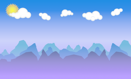
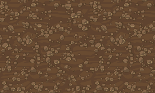
Don’t these kinda match the cartoony Worms art style? They go well together, but also maintain a strong enough contrast between each other that we won’t run the risk of muddying our foreground/background distinction. With those two textures loaded into our program, all we need to do is to sample from these two images at the corresponding x and y coordinates.
for( int x = 0; x < image.width; x++ ) {
  for( int y = 0; y < image.height; y++ ) {
    Array[int] color = [0, 0, 0];
    if( isSolid(x, y, image.width, image.height) ) {
      color = groundTexture.getPixel(x, y);
    } else {
      color = skyTexture.getPixel(x, y);
    }
    image.setPixel(x, y, color);
  }
}
Without the procedural texture generation, our code has gotten a bit simpler again. Because the two textures provided above already match our canvas size, we are able to simply pass x and y values along to them unchanged, but if they were tiling textures it would not have been much more difficult – we would have used the modulo operator to map the world coordinates to repeating texture coordinates, like so: color = skyTexture.getPixel(x % skyTexture.width, y % skyTexture.height);
In any case, here’s the result:
As much fun as it can be to muck around with simple generative textures, I gotta admit these pre-made ones have a really nice feel to them. Now the only issue is that our dirt layer is looking a bit flat. Maybe we can do something about that! With that goal in the back of our heads, it’s time to think about the order in which we’re drawing our pixels.
Thus far, all the calculation and color setting that we’ve been doing for each x and y coordinate pair has been independent. Each pixel gets set without regard for its neighbors, or for how much of the image we’ve already calculated. All that we use as input is the specific coordinates. To use a bit of computer science terminology, the inside of our main loop is side effect free. A common convention is for pixel images to be described line by line going from top to bottom, but we could have drawn our pixels in any order we wanted.
Depending on your level of programming experience, you may have just had one or several of the following thoughts:
- “Huh, that means we could swap our two
forloops inside out and nothing about the result would change.” - “Huh, that means our program would work super well as a shader.”
- “Huh, I remember how BMP files would for some reason be stored bottom to top.”
Sadly, only the first one is relevant for the purpose of this article. If you have the scanline model of image storage rather ingrained, like I have, you may have subconsciously thought that we were drawing our image line by line from top to bottom. But if you actually look closely at our loops, that’s not the case:
for( int x = 0; x < image.width; x++ ) {
  for( int y = 0; y < image.height; y++ ) {
    ...
It so happens that by arbitrarily starting the loop on x before the loop on y, we are currently drawing our images column by column! We start at the top left corner, then move downwards drawing each pixel as we go, then when we reach the bottom of the image we move one pixel to the right and start again at the top.
Why am I making such a big deal out of this if the order of the pixels doesn’t matter anyway? Well, it is about to start mattering. To do some shading, we’re going to break away from our elegantly independent draw operations and introduce some side effects. 😈
for( int x = 0; x < image.width; x++ ) {
  int depth = 0;
  for( int y = 0; y < image.height; y++ ) {
    Array[int] color = [0, 0, 0];
    if( isSolid(x, y, image.width, image.height) ) {
      depth++;
      color = groundTexture.getPixel(x, y);
    } else {
      depth = 0;
      color = skyTexture.getPixel(x, y);
    }
    image.setPixel(x, y, color);
  }
}
With this change, we now have a depth variable that keeps track of how many uninterrupted pixels of solid ground we have experienced. It starts at 0 at the top of each pixel column, then for every pixel we draw, it either gets incremented if it’s solid or set to 0 if it’s air. Can you see where I’m going with this? What if we use this variable to detect whenever we’re near the top of some solid ground and do something special in that case?
for( int x = 0; x < image.width; x++ ) {
  int depth = 999;
  for( int y = 0; y < image.height; y++ ) {
    Array[int] color = [0, 0, 0];
    if( isSolid(x, y, image.width, image.height) ) {
      depth++;
      if( depth <= 3 ) {
        color = [255, 0, 0];
      } else {
        color = groundTexture.getPixel(x, y);
      }
    } else {
      depth = 0;
      color = skyTexture.getPixel(x, y);
    }
    image.setPixel(x, y, color);
  }
}
With this change, the first three pixels of every solid part of any pixel column should be colored bright red. I’ve also preempted a small issue by initializing depth to some high value rather than 0. If we did not do that, we would see our special red pixels every time a solid piece of the landscape touched the top of the canvas, which isn’t what we want. Let’s see the result.
So simple, but so effective! If we now go ahead and come up with a way to draw a little bit of lighting on these first few pixels (maybe a few more than just three), it’ll be a huge boon for making the foreground feel tangible.
But to make the lighting look good, it won’t be enough to simply replace the ground texture with completely new colors. We’re going to want to blend our highlight color with the existing texture. So how about this: we define a top highlight as a list of colors for the topmost ground pixels, but in addition to the RGB channels, we also supply an opacity value (also called alpha value) between 0 and 1. That would allow us to mix the highlight color with the existing texture as we draw and create a smooth semi-transparent gradient for the lighting.
for( int x = 0; x < image.width; x++ ) {
  int depth = 999;
  for( int y = 0; y < image.height; y++ ) {
    Array[Array[int]] topHighlight = [
      [255, 245, 200, 0.7],
      [255, 245, 220, 0.5],
      [255, 245, 220, 0.3],
      [255, 245, 220, 0.2],
      [255, 245, 220, 0.15],
      [255, 245, 220, 0.1],
      [255, 245, 220, 0.05]
    ];
    Array[int] color = [0, 0, 0];
    if( isSolid(x, y, image.width, image.height) ) {
      depth++;
      if( depth <= topHighlight.length ) {
        for( int c = 0; c < 3; c++ ) {
          color[c] = topHighlight[depth-1][3] * topHighlight[depth-1][c] + (1 - topHighlight[depth-1][3]) * groundTexture.getPixel(x, y);
        }
      } else {
        color = groundTexture.getPixel(x, y);
      }
    } else {
      depth = 0;
      color = skyTexture.getPixel(x, y);
    }
    image.setPixel(x, y, color);
  }
}
For the RGB channels, the entries in topHighlight all contain the same values making a sort of warm yellow-white. When blending daylight colors like this, using a warm off-white usually looks better than stark white. I have it starting off at 0.7 opacity and then reducing pretty quickly at first, then slower as the list goes on. That means the color blending will not be linear, but sort of rounded.
The actual mixing happens in the innermost for loop. Each RGB component is individually blended between the highlight texture and the ground texture according to the alpha value at that specific depth. It would have probably been viable to generate that list procedurally instead of writing up the entries one by one like this, but I am preparing for future grassy ambitions here.
Yeah, that looks pretty good! It helps a lot for making the terrain look like something tangible that exists in the world with the background. Now, can we do the same thing for the underside of the terrain blobs? Thanks to our fade value we tend to have fewer of them than we do top sides, but it would still be nice to have some shadows there.
Well, since we’re traversing the image top to bottom, we can’t use the same depth trick. We’ll have to do something where we watch for transitions from solid to air and, once we encounter one, draw our shadow on top of the previous few pixels. It’s more cumbersome, but we can do it.
for( int x = 0; x < image.width; x++ ) {
  int depth = 999;
  for( int y = 0; y < image.height; y++ ) {
    Array[Array[int]] topHighlight = [
      [255, 245, 200, 0.7],
      [255, 245, 220, 0.5],
      [255, 245, 220, 0.3],
      [255, 245, 220, 0.2],
      [255, 245, 220, 0.15],
      [255, 245, 220, 0.1],
      [255, 245, 220, 0.05]
    ];
    Array[Array[int]] bottomHighlight = [
      [50, 35, 0, 1.0],
      [50, 35, 0, 0.8],
      [50, 35, 0, 0.6],
      [50, 35, 0, 0.45],
      [50, 35, 0, 0.3],
      [50, 35, 0, 0.2],
      [50, 35, 0, 0.1]
    ];
    Array[int] color = [0, 0, 0];
    if( isSolid(x, y, image.width, image.height) ) {
      depth++;
      if( depth <= topHighlight.length ) {
        for( int c = 0; c < 3; c++ ) {
          color[c] = topHighlight[depth-1][3] * topHighlight[depth-1][c] + (1 - topHighlight[depth-1][3]) * groundTexture.getPixel(x, y);
        }
      } else {
        color = groundTexture.getPixel(x, y);
      }
    } else {
      if( depth > 0 ) {
        for( int yBack = y - 1; yBack > 0 && y - yBack < depth && y - yBack - 1 < bottomHighlight.length; yBack-- ) {
          Array[int] shadedColor = image.getPixel(x, yBack);
          int index = y - yBack - 1;
          for( int c of [0, 1, 2] ) {
            shadedColor[c] = bottomHighlight[index][3] * bottomHighlight[index][c] + (1 - bottomHighlight[index][3]) * shadedColor[c];
          }
          image.setPixel(x, yBack, shadedColor);
        }
      }
      depth = 0;
      color = skyTexture.getPixel(x, y);
    }
    image.setPixel(x, y, color);
  }
}
We define bottomHighlight as a gradient of warm brown/black from full opacity towards full transparency. When we encounter a pixel of air while depth is not 0, that means we just hit the first air pixel after at least one ground pixel. We define a helper variable yBack, which we use to traverse a short distance back up the image, blending our bottom texture colors into whatever was already rendered. When you implement this yourself, watch out for off-by-one errors in the array indexing, and keep in mind that bottomHighlight is effectively drawn in reverse compared to topHighlight.
Our shading and lighting result now looks like this:
That looks satisfyingly shaded. We’ve really improved the tangibility of our terrain using just the fairly simple touch of painting on a sliver of shadow wherever the ground has a bottom edge. And you may have noticed that we don’t take curvature into account at all – any lighting and shading we do is based on individual columns of pixels. As a side effect of that, the effects look as if they’re lessened on slopes. Another happy coincidence!
Alright, we’re getting pretty close to finishing up. But because our landscape is still looking a bit barren, I have one more trick up my sleeve. What if, instead of a translucent gradient for lighting, we try painting some grass along the top? Here’s a tiny little grass texture I came up with in my image editor:
It’s ten pixels high in total, with a bright green base grass color framed by a darker shade above and below, turning into a darker bluish green for the shadow and then into a translucent red-brown shadow for alpha blending. That should fit the art style we’ve got going on. I can copy and paste the RGB and transparency values from my image editor into the topHighlight variable and be done with it.
Except that I have one more detail I want to try for this version. If we use this texture as-is, it will look smoother than we want, more like green plastic than vegetation. We can introduce just a tiny little bit of procedural randomness to make it look more like blades of grass, by randomly offsetting the texture by one pixel half the time. With that little modification, here is our final code:
function isSolid( int x, int y, int width, int height ): boolean {
  float xRel = x / width;
  float yRel = y / width;
  float frequency = 3.0;
  float fade = 0.5;
  float threshold = 0.5;
  float value = fade * (y / height) + (1 - fade) * simplex(xRel * frequency, yRel * frequency);
  return value >= threshold;
}

for( int x = 0; x < image.width; x++ ) {
  int depth = 999;
  int topHighlightOffset = randomRange(0, 1);
  for( int y = 0; y < image.height; y++ ) {
    Array[Array[int]] topHighlight = [
      [9, 144, 15, 1.0],
      [19, 183, 26, 1.0],
      [19, 183, 26, 1.0],
      [9, 144, 15, 1.0],
      [10, 120, 15, 1.0],
      [12, 110, 51, 1.0],
      [15, 75, 39, 1.0],
      [48, 21, 20, 0.75],
      [48, 21, 20, 0.5],
      [48, 21, 20, 0.25]
    ];
    Array[Array[int]] bottomHighlight = [
      [50, 35, 0, 1.0],
      [50, 35, 0, 0.8],
      [50, 35, 0, 0.6],
      [50, 35, 0, 0.45],
      [50, 35, 0, 0.3],
      [50, 35, 0, 0.2],
      [50, 35, 0, 0.1]
    ];
    Array[int] color = [0, 0, 0];
    if( isSolid(x, y, image.width, image.height) ) {
      depth++;
      if( depth + topHighlightOffset <= topHighlight.length ) {
        int index = depth + topHighlightOffset - 1;
        for( int c = 0; c < 3; c++ ) {
          color[c] = topHighlight[index][3] * topHighlight[index][c] + (1 - topHighlight[index][3]) * groundTexture.getPixel(x, y);
        }
      } else {
        color = groundTexture.getPixel(x, y);
      }
    } else {
      if( depth > 0 ) {
        for( int yBack = y - 1; yBack > 0 && y - yBack < depth && y - yBack - 1 < bottomHighlight.length; yBack-- ) {
          int shadedColor = image.getPixel(x, yBack);
          int index = y - yBack - 1;
          for( int c of [0, 1, 2] ) {
            shadedColor[c] = bottomHighlight[index][3] * bottomHighlight[index][c] + (1 - bottomHighlight[index][3]) * shadedColor[c];
          }
          image.setPixel(x, yBack, shadedColor);
        }
      }
      depth = 0;
      color = skyTexture.getPixel(x, y);
    }
    image.setPixel(x, y, color);
  }
}
Aaaand that’s it! We have some grassy looking highlights on our procedural landscapes.
I don’t know about you, but I’m ready to call things done in this state. If you scroll back up and compare this to the Worms 2 screenshot, I think we’ve gotten pretty close. Alright, let’s finish up this journey.
Final Results
To recap:
- We have used simplex noise to generate collision masks suitable for 2D pixel landscapes.
- We defined frequency, threshold and fade parameters that let us fine-tune the generated landscapes.
- We have gone from plain colors to simple procedural textures and to full painted ones.
- We have introduced a simple highlight system that lets us dynamically add surface detail.
Not bad for one blog article, I would say! And the result really does look pretty close to what we set out to imitate. Here’s a final little playground for you, where you can tweak all our parameters to your heart’s content and see what comes out the other end. Remember that you can click the image to reshuffle the simplex noise. If you find a landscape you particularly like, feel free to right click and save, it’s yours to keep!
If this has gotten you motivated to do some creative stuff with simplex noise or to come up with some other way to make procedural terrain, I wish you the best! Here’s some food for thought for possible steps after this:
- So far we have a simple, linear fade function from the top of the landscape to the bottom. But Worms levels were usually islands or enclosed caves, so you’d be unable to walk out the side. How could our fade function be modified to make sure the left and right sides are all solid or all air?
- Part of the fun of Worms and other games like it is the destructible world. Assuming you’ve generated some terrain and you have a copy of the collision mask, how would you blow a circular hole somewhere into the terrain and how would you update the final render result?
- We’ve been working with two-dimensional simplex noise, but generating higher-dimensional noise is no trouble. What would you do with three-dimensional simplex noise? Can landscapes be made out of it? What would they look like and what kind of gameplay would they be suitable for?
This has been my first blog article about game development, and also my highest-effort blog article ever, by some margin. I learned how to do a bunch of new things in three.js for this! If you enjoyed it or found it helpful, I would appreciate it if you shared it in whatever game dev / indie dev community you’re a part of. I would like to thank Christina for her feedback on a draft version of this article, and Bamboy for inspiring me to properly write all of this down by posting a thread on his own (completely different) approach. More feedback is always appreciated – you can leave a comment, contact me on Mastodon, or send me an email. That said, there are absolutely no guarantees for what I’ll write about next. This blog is a pretty big topical catch-all for my interests and the next article will, statistically speaking, most likely not be about game development. We’ll see what happens. For now, thanks for reading!
Comments
You can leave a comment by replying to this Mastodon post from your own account on Mastodon, GoToSocial, Akkoma, or any other ActivityPub-capable social network that can exchange replies with Mastodon.